Rhea agreed that yo-yo's would make nice presents for the grandsons on Hanukkah. An article from Home Shop Machinist vol. 38, no. 4, pg 60 was the inspiration and will be followed to make the yo-yo's. They are made from aluminum, a simple turning project, and have a buried ball bearing enabling easier "sleep" mode.
Four aluminum blanks are needed to begin the project. After checking SpeedyMetals and finding a foot of 2 1/4" round 6061 aluminum cost over $60 plus $20 shipping, I looked elsewhere. Metal Supermarkets has a facility on W. 79th St. I called the store, 317-584-8555, and a few hours later I received the quote for < $60. It can be picked up early after they call. This was done and I am now the proud owner of a one foot long round bar of aluminum.
The next part of the project tackled was making the form tools. I found a 1/8" X3/8" bar of HSS in the hoard of material Klaus Schmiegel gave me. I marked out a 1/4" radius arc on each end, one for right hand and one for left hand cutting. The arcs were ground with a 5° relief on the grinder first with the coarse and then fine wheels.
At this point I realized I had no way to hold this cutter in the lathe, so it is time for the titular diversion. Klaus also gave me a lathe tool holder that has a slot on each side for a tool. The holder does not have a tee nut or screw. It is also significantly too low to hold the form tool on center. So three parts were made. The first was the simplest, a 1/2" thick disk of aluminum to raise the holder, essentially a thick washer the holder will sit on. The washer was drilled 13/32", a through hole for the eventual 3/8-16 screw.

The nut was made next, also from an aluminum disk. The shoulders of the nut were formed with the shaper. The shaper worked well and left a nice finish after the tool was reground and honed on the diamond stone. The nut was drilled to 1/2" and then countersunk on the bottom side. A bronze insert was made to fit in this hole and it was threaded 3/8-16 with a tap. The insert was held in place with LocTite. The round edges were cut off with a hack saw and then milled to the 1 1/4" width of the compound's opening.

The final part needed is a screw. I had no appropriate screws for use. I also didn't want to use a standard screw as that would require having yet another wrench handy. I found some 3/4" hex that fits the homemade wrench kept on the tailstock. A 4" length of this was cut off with the bandsaw. One end was faced and heavily chamfered. The tool was then held by this end in the chuck and the distal end was center drilled, while supporting this end with a tailstock center, 2 1/2" was turned down to 0.370". This end was chamfered and then threaded 3/8"-16 for about 3/4". The threading went easily after realizing the die I initially attempted to use is for left hand threads! After some clean-up the parts were assembled on the cross slide. The screw needed the threaded end shortened by about 1/4". About 3/16" was cut off with a hacksaw and the end was filed to clean up the threads. A perfect fit and gives a very tightly held holder with minimal force.


The tool was tried out this morning. It was placed in the tool holder and raised with a 1/16" shim to get it on center. A scrap was set up in the lathe chuck. The tool worked fine, though there was significant chatter or squeal as expected. The surface finish has grooves indicating that the tool is not ground well. I am not sure this is any easier than using a file to round the corners. The photo below shows the result.

The process in the article was followed for the first yo-yo side. A 9/16" thick disk of aluminum was cut off with the bandsaw. This was faced on one side and drilled 0.30" deep with a #29 drill. It was threaded 8-32 using the recently purchased bottoming tap. The hole was then countersunk with a 3/8" end mill held in the drill chuck. The countersink was done slowly and frequently measured so the total depth is 0.020". The disk was flipped over and the opposite side faced. A boring bar was used to make a 1/8" deep by 1 3/4" recess.


The process above was repeated to complete the drilled and tapped side for the five remaining blanks. The first photo shows the nice finish resulting from careful facing. The finished sides on five parts are shown in the second photo below.


The next morning in an even colder garage the opposite sides were bored, again to 1/8" X 1 3/4". This went well, though doing it five times became a bit repetitive. The six parts at this stage are pictured below.

The final machining step is cutting the corner curves. Getting ready to utilize the corner rounding tool made above and discovered the chuck jaws when closed are still too large for the bored hole in the side! These corners will have to be cut on the Sherline lathe. Cutting a feature like this on the small lathe with a form tool will potentially overtax the machine. I will first try using the radius cutting tool. This won't work as the tool is limited to 1 1/2" diameter. A part was held in the cleaned three-jaw chuck with the jaws reversed. It was first filed and then sanded to give the shape seen below, significantly less than 1/4" radius. The part will need to be held between pads, or between pad and tailstock center, to work both sides.

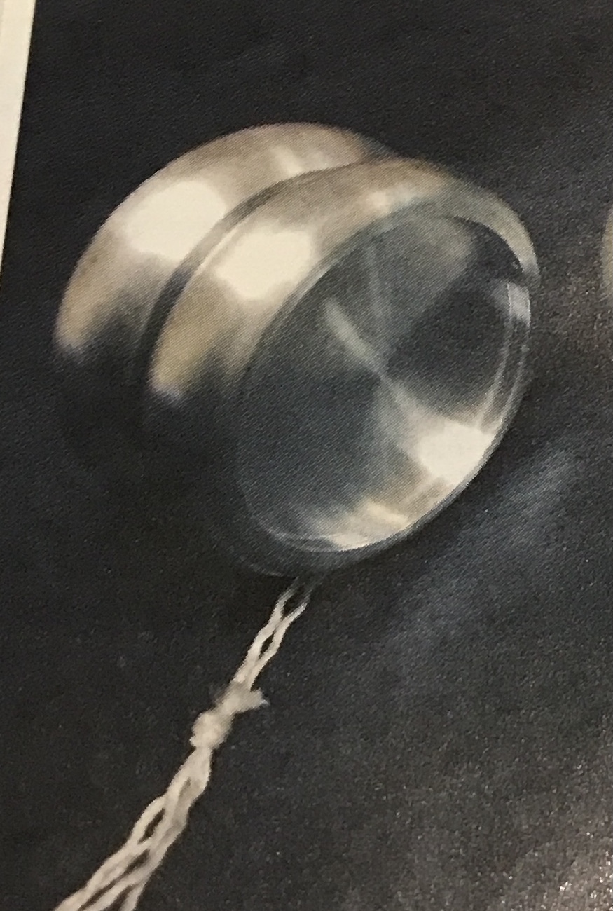
The part was held between a pad in the chuck and the live tailstock center. It was filed, and sanded up to 1500 grit. It was then polished with the buffing wheel using white buffing compound. The photo shows the "yo" after washing with soap and water.

An attempt was made to better polish the second "yo". First it was sanded with the coarser crocus cloth, the corners were filed and resanded with fine crocus cloth. This was polished on the buffing wheel as before. It seemed impossible to get rid of the slightly cloudy polished areas at the edges of the recess. A Dremel polishing wheel loaded with white rouge did the trick, but left a slightly different finish. The photo below compares the two "yos", with the first on the left. The 8-32 set screw did not go into either wheel until the holes were hit again with the tap. Then the bearing (9mm X 4mm X 3mm) did not fit over the set screw!! The screw will need some adjustment.

Another pair were sanded and polished this morning. The sides were sanded up to 2000 grit using a four-jaw chuck. The edge was filed and the corners chamfered and rounded with the file. The edge was sanded up to 2000 grit. The inside, the edge and the lip of the recess were polished on the buffer. The center of the recess was also polished with the buffer. The Dremel was used with rouge to polish the areas of the recess the buffing wheel could not access. The photo below shows the finished pair of "yos".

After reducing the diameter of a set screw by about 0.004" it fit nicely in the bearing. The length also had to be reduced by about 1/8". The two yos were screwed onto the set screw with the bearing trapped between. A string was wrapped around the bearing (difficult to get the string wrapping started) and the yo-yo was tried out. The author mentions the yo-yo is probably too heavy. I also found this to be the case as it was difficult to get the yo-yo to climb back up the string. Reducing the weight will take some consideration.
The most straightforward path would be boring a groove in the inside face of each yo. A groove that begins at 1/4" radius and extends 3/8" and is 1/4" deep would be about the limit of removable material. A groove like this leaves about 1/8" of material in the bottom of the groove before the groove on the front face. A little math indicates this will remove about 15% of the volume of a yo. So the weight of a yo-yo will drop from 148 g to 126 g. Is this sufficient? Most of the yo-yos on Amazon are 50-60 g, but a professional version is 257 g. Drilling holes through is another possibility. Replacing the groove with a hole circle centered between the sides of the groove has a circumference of 1.37", which would allow 3.66 3/8" holes to be drilled. Smaller holes would be necessary and the extra weight removed would be minimal.
Based on the shape of some yo-yos on the internet a second possibility for mass removal is slicing off a wedge shape from the inside face creating a cone of sorts. Starting at 1/2" diameter and cutting all the way to the edge so only 1/8" remains on the edge, i.e. a 3/8" X 7/8" triangular cross section, removes 42% of the weight. The yo-yo would then weigh about 86 gms. This would be a 23.2° bevel angle.
The compound was installed on the Sherline lathe after filing a too thick tee nut. The compound was set to 67°. Cutting was done by moving the the carriage back 0.010" in the y-direction. A pass was made. Care had to be taken as the cutter approached the outside edge of the workpiece. If moving too fast the yo would pop off of the chuck, as it is only held on by 1/8". The cutting was slow, but effective. The cutting was stopped when the inside diameter was 1/2". This left a slightly larger than 1/8" rim thickness. The first photo shows the cut in progress and the second compares the finished cut to a full width piece.


The bevel was repeated on a second part. The edges were cleaned up with file and sandpaper. The parts were not sanded, but went straight to the buffing wheel. The yo-yo after polishing and cleaning is shown below. This yo-yo is certainly a lot lighter than the previous and still spins nicely on a string. However, with the bearing in place I cannot get the yo-yo to rise back up the string. Winding the string is also difficult.

The bearing was replaced in the angled yo-yo with a bushing made from brass tube. The tube is 0.25" OD and 3/16" ID. It was cut off at 0.15". The yo-yo now functions correctly, but does seem to readily hang at an angle. The two halves were measured at 40 and 43 grams. How close do they need to be? A rough approximation of the amount of material to remove goes as follows. The width of the yo is 1.25 cm, so the area of its unreduced perimeter is 1.25 X π X 5.7 = 22.4 cm2. Removing 0.05 mm would drop the weight by 3 gms. These yos with a 1/8" wide perimeter require reducing the diameter by .2 mm, which would be noticeable, so any material removed needs to come from the face or the interior angle.
Alternatively, removing a centimeter from the reduced section of the face would decrease the weight by 4.19 gms. Removing 0.028" will remove 3 grams of aluminum. Back to the lathe. The heavier half was chucked in the three jaw chuck on the South Bend lathe after making new soft jaws from an old license plate. A few minutes was spent aligning the yo and then 0.025" was removed from the bore with a boring bar. The yo now weighed 41 gms. The yo was polished and washed. After assembly the yo-yo was tried out. It no longer twists to one side, success!
There is no good way to hold the yos with rounded corners for cutting the angle. Two new yos were made this morning on the South Bend lathe. The blanks were cut 5/8" thick and then faced, drilled and countersunk. After flipping the opposite side was faced and the width was reduced to 1/2". This opposite face was bored as above.
The next morning each yo was held in the Sherline via the bored face. The compound was set at 67° and 0.0075" cuts were made across the inside face until the edge was 1/8" wide. The edges were sanded at this point. Both yos were polished as before and then washed with soap and water. They are shown in the photo below. They were weighed and both weighed 42 gms. A piece of brass tube was parted off at 0.150". A set screw was shortened to 0.60" and the second yo-yo was assembled. Works like a charm.


Boxes for the yo-yos were next. The plan is to make custom boxes with cutouts for the yo-yos, extra string, and the bearing. If the kids get really good, they can figure out how to use the bearing. Some wood was selected, red oak and mahogany(?). Both the lid and box will be made of two layers of contrasting wood. The wood was cut to approximate size, 3 1/4 X 4 3/8". After cutting the wood to size the wood was glued together as seen in the next two photos. The blanks were removed from the clamps after two hours, but won't be worked until tomorrow.


After removing the clamps the blocks were held on the workbench and planed. This did a good job producing smooth surfaces, but left the edges angled. My planing technique is poor. The one lid part was planed to remove glue squeeze out and then glued to one of the three dark/light glued blocks sandwiching the darker wood as seen below. After significant wood removal this block will become two lids.

The blocks were cut to size on the table saw. The large double top block was difficult to cut to size without leaving 1/2" or so of a ridge as I didn't want to set the blade high enough to cut all the way through in one pass. This block was finished on the belt sander. The before and after shots are seen below.


The holes will be drilled and then the blocks will be sanded. Drilling the holes for the yo-yos is problematic. I don't have a sufficiently large hole saw. The largest is 2 1/4", which is the diameter of the yo-yos. I have an adjustable hole saw, shown below, which can be opened to 2 1/2", slightly more than the 2 3/8" desired. The drill that is integral to this saw is long enough to cut through the block as the hole reaches depth. (The goal is to completely bury the yo-yo in the block.) Two other possibilities for making the holes are by boring on the South Bend lathe or by milling with the aid of a rotary table. In any of these approaches the hole center will be 1 7/16" in from the short side of the block and centered between the long sides.

Decided not to use the hole saw as I didn't want to plug a hole in the bottom of the box. Instead the lathe was used. The center of the desired hole was marked and the block was placed in the four jaw chuck with the hole on center as determined by a tailstock center. First a hole was drilled with a 1 1/8" spade bit to a depth of 1". This depth ensured that the point of the bit did not penetrate the box bottom. The hole was then widened and deepened with a boring bar in 0.020" depth increments. The garage shop was cold, so only one block was completed. The hole was bored to a depth of 1.20" and is a nice fit for the yo-yo, leaving room for eventual felting.

The second hole was finished this morning in an even colder garage. After sanding off the fuzzies, the two boxes and matching lids are shown below. I am no longer sure the lighter wood is red oak. The sawdust is definitely yellow! However, it does smell like oak. The next steps are drilling the other two holes in each box and then affixing lids. A 3/4" hole is planned for the extra string and a 3/8" hole for the bearing.

Both holes were marked 3/4" in from the short side and 3/4" in from the long side. They were drilled for the 3/4" hole with a spade bit and with a brad point drill bit for the smaller hole. After a bit of sanding around the hole edges the drilled blocks are shown below.

The lid will rotate to open, attached via a wood screw in one corner. The opposite corner will hold a magnet and a piece of steel, one in the lid and one in the box. The screws will be round headed brass wood screws, which I don't happen to have. Off to Menards. The screws were purchased along with two other items for other projects. The next step was tapering the edges of the box tops. The table saw was raised 1" and tilted 10°. With the fence sitting close enough that the top of the blade was about 1/16" still in the wood of the top the tops were cut. The shorter ends were cut first followed by the longer sides in an effort to remove any tearout from the ends. This was successful as shown in the photo below.

The box tops were clamped to the boxes with two sides flush using a large pinch clamp. Using the belt sander the sides of the boxes were sanded until all sides and top edges were flush. The boxes at this stage are shown below.

More drilling, this time for attaching the lid. The lids were marked on the corner near the large hole and opposite the smallest hole 1/4" in from each edge. These distances were checked with a scrap of paper to make sure the box would rotate out of the way of the large hole and yo-yo removal. The box and lid were clamped on the drill press with the center punch in the chuck aligned with the mark. A flat was milled into the lid just enough to see a full circle with a 5/16" end mill. The box and lid were drilled about 1" deep with the drill for the minor thread diameter of these #8 screws. The lid was then drilled for the major diameter as a through hole. On the opposite corner a second hole was drilled for a short #8 screw and countersunk, 5/16" in from each edge. After dropping and losing the pieces of steel cut off for the magnet, screws were substituted. The photo below shows the results of this effort. Only the hole for the lid magnet remains.

The magnets and covers were next. Each of the lids was held on the milling vise with strap clamps. The marked spot was centered under the spindle and drilled with a 0.189" drill to 0.188" deep as determined by setting the drill point even with the surface of the lid. The drill was switched for a 1/4" end mill, which opened the hole and provided a flat bottom. A 1/2" end mill was used to make a 1/16" deep countersink. The magnets didn't quite fit so the holes were reamed with a 1/4" reamer. A compass was used to draw two 1/2" diameter circles on a scrap of 1/16" veneer left from the veneered box class. The circles were cut out with a chisel and sanded to size. Two part epoxy was prepared and spread into the hole. An air gap was made at the edge of the 1/4" hole, then the magnet was pressed in place. A bit more epoxy and the circle of veneer was pressed into the countersink serving as a cover for the magnet. The steps of this process are seen in the three photos below.


Lots of sanding this morning. The bottoms of the lids where the magnet and veneer were proud was sanded on the belt sander. The bottoms and the lids were sanded all over with 150- and 220-grit paper, about fifty strokes per area. The end grain on both lids and bottoms were further sanded with 320- and 400-grit paper. The edges were all lightly chamfered with 220-grit paper. The sanding table was utilized and again did a great job of minimizing dust in my nose. The dust on the parts was first removed with vacuum and then with air blown from the vacuum vent port. After finding no shellac in the house, wipe-on polyurethane was selected as the finish. A first coat was wiped on. The two photos below show the sanded and the first coat of wipe-on poly.


The poly must wait 2-3 hours before the next coat and has to be lightly sanded with 220-grit paper between coats. Two more coats were applied with light sanding between each coat. I am not thrilled with the finish. The poly does not seem to build up and the finish looks dull. I will let it dry for a couple of days and apply some paste wax. That may provide the sheen I am seeking.
Felting was explored by cutting a piece of felt with scissors 1 1/8" X 7 1/2". This was wrapped around the inside of the large hole. It needed 1/4-3/8" removed to fit. A yo-yo slid in with no room to spare. Removing the yo-yo reminded me that I need to put a notch in the side of the hole to make yo-yo removal easier. The poly does not seem completely dry, so notch filing will wait a day or so minimizing the dust sticking to the finish.


Paste wax was applied to the yo-yo boxes and then buffed out. After two days finger prints are still left on the finish?! The notch was filed and then sanded in the side of the large hole as seen in the photo below.

Instead of carving the boy's names into the box tops an engraved plaque will be used. Two brass blanks were cut from a sheet of 1/32" brass. They were approximately 1" X 2", sized to fit on the center raised portion of the tops. The corners were rounded with a file and the edges deburred. China white was applied and the boy's names were written on to the plaques with a pencil. The names were then engraved with a freshly sharpened 105° chisel. The names engraved onto the brass can be seen in the photo below.

After some indecision on the best way to attach the plaques the following was chosen. A simple jig was made using carpet tape to hold two blocks of wood onto a wood base forming a right angled pocket. This jig was held in the milling table vise and the spindle was aligned 0.12" in from each side of this angle. A plaque was held in the jig against this corner and drilled with a #32 drill, 0.116". All four corners of both plaques were drilled in a few minutes. The holes were transferred to the box lids, drilled with a #42 drill, and tapped 4-40. The first photo below shows a drilled plaque resting on the simple jig. The second shows an unpolished plaque screwed in place on the box lid.


The brass plaques were first lightly sanded with 600 grit paper to remove burrs from the engraving. They were then polished on the wheel using red rouge. The steel screw heads were polished on a wheel using green rouge. Finally the brass screw heads were polished as well. All parts were cleaned, soap and water, followed by acetone and then painted with varnish (the steel screws were not varnished). A second coat of varnish was applied to the brass parts.
The boxes were felted next. Felt was found in the red tool chest in a few colors. Ruby was chosen for Levi's box and a bright blue for Ollie's. Pieces were cut 1 1/8" wide and trimmed to the length of the trial green piece cut earlier. A notch was cut about half-way along the strip to match the notches in the boxes. A square was cut out of each color felt as well at 2 3/8" on a side. These squares were trimmed to circles. Glue was squirted into the bottom of the large hole and spread around and up the sides. The circle was set in the bottom and the long rectangle was wrapped around the inside wall with the notches aligned. After a bit of straightening the felt was firmly pressed into place and left to dry. The photo below shows the two felted holes still wet with glue.

An attempt was made to complete the boxes this morning. The engraved plates were screwed to the box lid. A drop of epoxy was placed in the pivot screw holes and the screws were put in place. Glue squeeze out was carefully removed before tightening the screws to full depth. The lids turn nicely. The photos below show the boxes in both the open and closed positions.


Putting the yo-yos in place indicated a problem. The yo-yo in Ollie's box sits proud keeping the lid from seating on the box when closed. The gap is obvious and the magnet is now too far away to hold. Tightening the two halves of the yo-yo reduced its height from 1.125" to 1.105", still leaving the yo-yo about 1/64" proud. Either the hole must be made deeper, but I don't know how, or the yo-yo can be made shorter by taking off some material in the lathe and polishing the yo-yo again.
The reduction and polishing went reasonably well. The yo-yo now fits in the box with the lid closed. The photo below shows the two yo-yos in their boxes, bringing this project mostly to a close. As seen in the photo extra strings were cut, ends melted, and tied before placing them in the provided holes. I still plan on putting a screw through a bearing in the last hole, though I doubt it will ever be used.

The final task, installing the bearings was completed this morning. Two brass 1/2"-#4 screws were installed in the smallest holes with the bearings after pre-drilling the holes for the screws.